Cyberdeck X: I mugged a Cyberman
Steve rips the sock off the head of a 1960s Mondasian Cyberman and fashions it into stereo speakers!

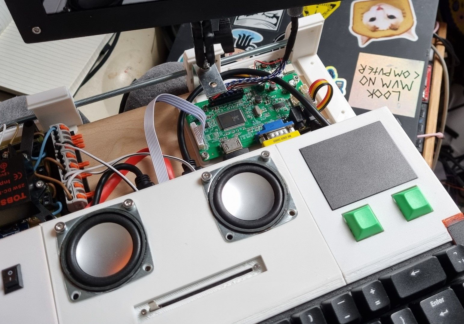
Been cracking on with things when I get the chance. Got audio output now as well as a bit of structural integrity at the back of the build.
Amp and speakers
In the last thrilling instalment I ran through what I was considering for the audio output. Bits arrived from China, so I got out the callipers for a bit of measuring (with mixed success), did some Fusion 360ing, soldered up components and ended up with this...
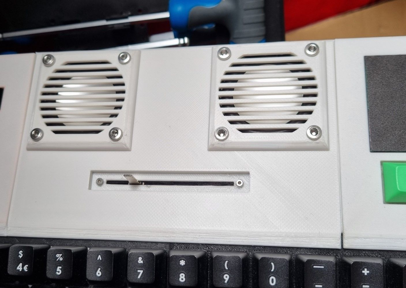
Looks ok! When it comes to painting the body I might leave the grills white for a bit of a feature contrast - not sure yet. The slider is the volume control, replacing the little thumbwheel thing that came with the kit because, well, that felt more like the daft sort of thing I'd do.
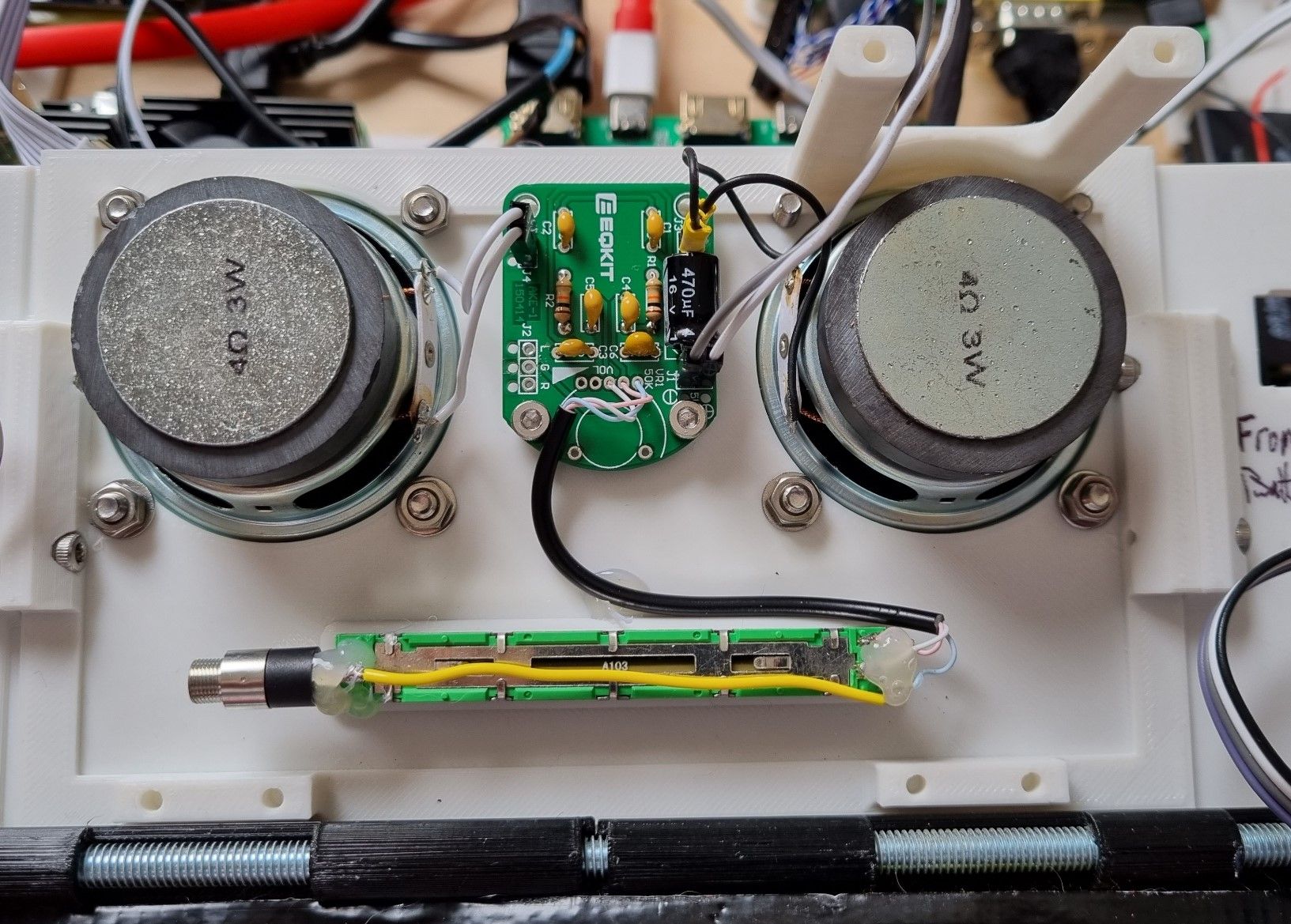
These speakers are quite heavy and punchy for the diminutive proportions, so I added some support legs which line up with an area on the base where there's some space. Naturally, I didn't consider adding enough space for the nuts to go on the bolts, and I also didn't think to make sure that the nuts would be on the flat on the other speaker. Final error was getting the measurement of the holes on the PCB wrong (as alluded to in paragraph 1 of this section) so it's being held in with only two of the four points. Hey ho.
Of note - the 3.5mm jack on the end of the volume control is where the audio gets into the amplifier and the grey and white leads are how it gets powered. I found a handy source of 5V for it to run off as well - more in the next section.
Obviously none of this would have any point if it sounded awful, but it's not bad at all. Once the whole case is complete and closed it should be rather good if the experiments I've done so far are indicative.
Screen driver mods
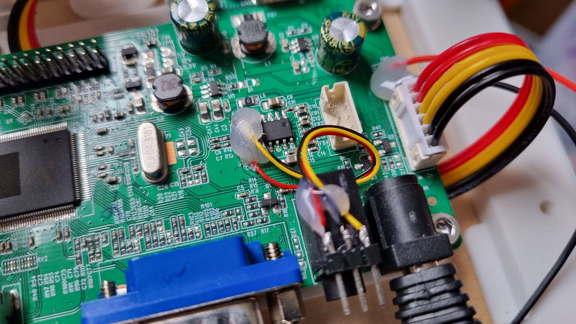
In the previous mind-blowing instalment I detailed what I'd found out about the HDMI audio's routing to the driver board's own amplifier circuit. I don't want to make destructive modifications where possible, so with the soldering iron heating the pads I slipped a scalpel underneath the power leads and lifted them clear. (I didn't want weirdness occurring with the unused chip potentially leaching current from the audio signals - hopefully that wouldn't happen anyway, but it took seconds to do.)
Wire wrapping wire was attached to the left, right and audio ground pins with the slightest dab of solder, then protected with a soupçon of hot glue once I'd made sure the joints were secure. A three pin header was superglued to the top of the audio-in jack and the wires attached accordingly. That did the job of extracting the audio perfectly, without having to add another box to the signal path.
I mentioned powering the amplifier; I wanted it to seamlessly switch on rather than having another switch (besides, I was running out of switches I could dedicate to such purposes). Initially I considered having it wired to both the Pi and the ZX Uno supplies, so that it would be switched on regardless... until I realised that without some extra work it would also switch on the other board regardless as well. No good. So I thought I'd have a peep at various pads on the driver board and see what I might be able to tap into - after all, its own amp circuit must be getting driven by about the same voltage.
I struck gold. Right next to the header providing the 12V for the backlight driver there were unused pads, labelled clear as day: "5V" and "Gnd". Wires were soldered, hot glue was oozed and the evidence is also on the photo just up there, on the right hand side. Huzzah!
Make you big and strong
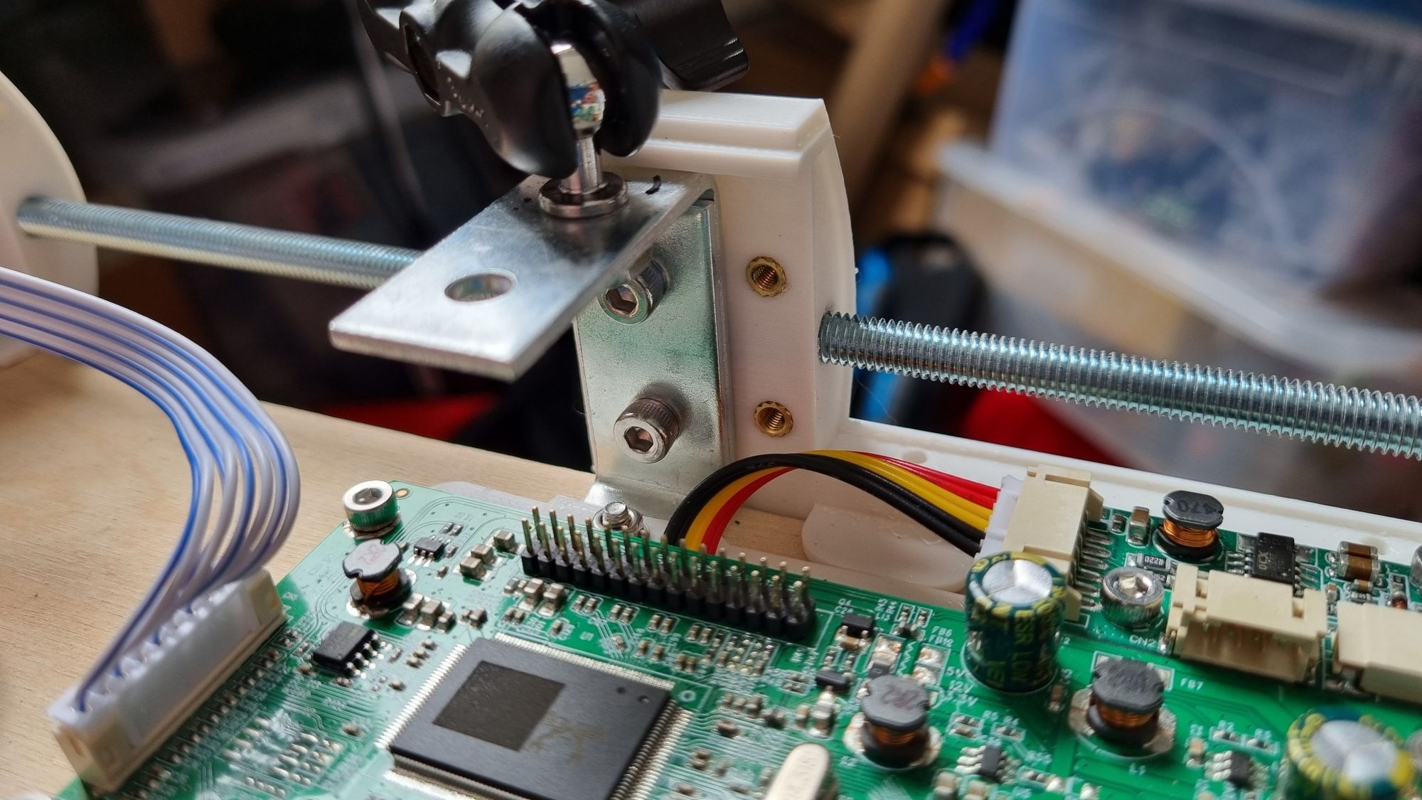
The bracket that the screen is mounted to needs to be nice and secure, otherwise the whole screen would be floppy and unusable. I redesigned the plate that holds the screen driver to allow the bracket to slip under in one spot, added pegs to line up with the holes and screwed it into place. With that done I got designing bits for the back, for another threaded rod to provide some solidity, and made a nice solid chunk that married up to the bracket. Two hot-set brass screw inserts provide a place for a front-piece to be attached and I'm planning on running that to the other side of the chunk, where I might end up having a carry handle. Either way, it's solid enough to hold tight - as I discovered when it fell on the floor (oops) and the screen came away from its ball joint before anything happened to this. (The screen is reattached with Gorilla Glue and ain't going anywhere now.)
What next?
Probably the most pressing thing to do is make the firmware for the keyboard much better. At present it's spewing out bytes to both PS/2 and USB at the same time rather than switching between the two, and it's doing a bit of a half-assed job for both as I try and get my head out of higher level code and start thinking in C++. At present neither the Fn key on the PS/2 interface, nor the Alt key on the USB interface, are working properly. The scanning routine seems adequate but my handling of modifiers clearly isn't! I also want one core to be doing the keyboard essentials, like the scanning and communications, with the other one handling the user interface on the display and any tasks relating to that - the display, being I2C, is a bit of a bottleneck in terms of speed and it makes sense to offload anything that will hit the matrix scanning.
That's it for now, kids. More fun soon!